Designing of PFD, P&ID, Isometrics, Equipment layout

1. Design of PFD (Process Flow Diagram):
- Process Mapping: Identify and map out the entire process involved in the project. Define key steps, components, and interactions within the system.
- Symbolic Representation: Use industry-standard symbols and notations to represent various elements such as equipment, instruments, valves, and piping in the PFD. Ensure consistency and clarity for easy interpretation.
- Collaboration: Engage in collaborative discussions with process engineers, stakeholders, and other relevant parties to refine and validate the process flow.
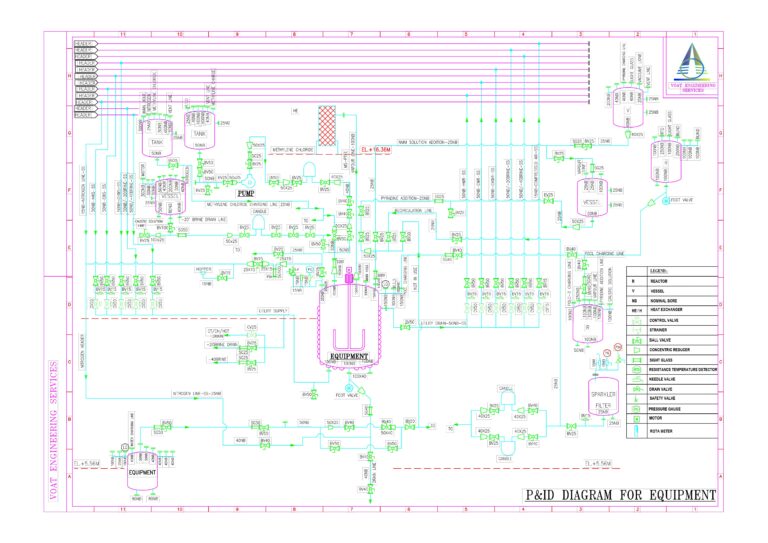
2. Design of P&ID (Piping and Instrumentation Diagram):
- Detailed Piping Layout: Develop a detailed representation of the piping system, including pipe sizes, materials, and routing. Clearly define connections, valves, instruments, and equipment.
- Instrumentation Details: Include instrumentation symbols, indicating sensors, transmitters, controllers, and other relevant instruments. Specify measurement points and control loops.
- Safety Considerations: Incorporate safety features and emergency shutdown systems into the P&ID. Ensure compliance with industry standards and regulations.
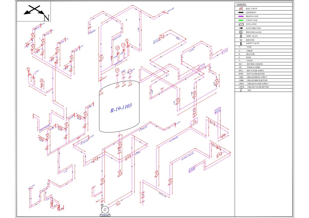
3. Isometrics (Isometric Drawings):
- Detailed 3D Representation: Create detailed isometric drawings that provide a three-dimensional representation of the piping system. This aids in visualizing the layout and identifying potential clashes.
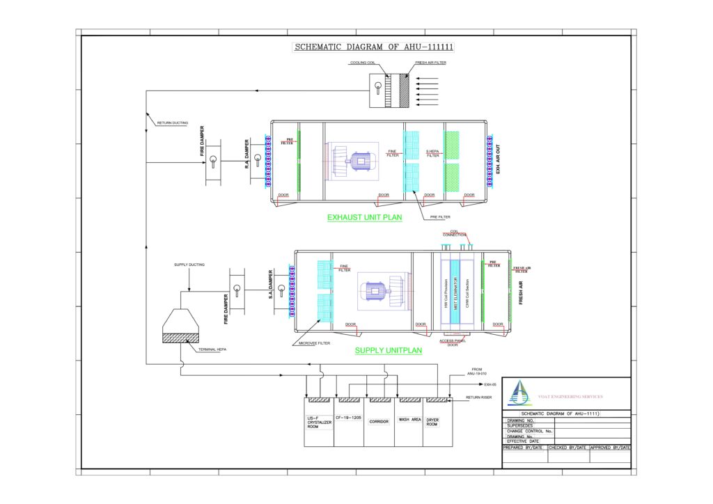
4. Equipment Layout:
- Spatial Arrangement: Determine the optimal placement of equipment within the facility. Consider factors such as operational efficiency, safety, and accessibility during maintenance.
- Clear Annotations: Provide clear annotations and labels for each piece of equipment, indicating specifications, dimensions, and any special considerations.
- Compliance: Ensure that the equipment layout adheres to relevant safety standards, building codes, and regulatory requirements.
5. Visualization and Presentation:
- 3D Modeling: Utilize advanced 3D modelling software to create realistic visualizations of the proposed designs, allowing clients to better understand the layout and appearance of the final facility.
- Presentation Materials: Develop visually appealing presentation materials, including renderings, animations, and diagrams, to effectively communicate the proposed designs to clients and stakeholders.
By integrating a comprehensive proposal process with detailed design methodologies for PFD, P&ID, Isometrics, and Equipment Layout, a consultancy company can demonstrate its ability to deliver precise and effective engineering solutions for diverse projects. This approach helps build client confidence and sets the foundation for successful project execution.